That depends on their configurations. For example:
While it makes very good sense to include redundant physical links in a network, connecting switches in loops, without taking the appropriate measures, will cause havoc on a network. Without the correct measures, a switch floods broadcast frames out all of its ports, causing serious problems for the network devices. The main problem is a broadcast storm where broadcast frames are flooded through every switch until all available bandwidth is used and all network devices have more inbound frames than they can process.
Originally this challenge was with bridges. Though switches have replaced bridges in most organizational networks, the solution is the same. Radia Perlman’s STA (Spanning Tree Algorithm) fix for bridge loops also works for switch-based networks:
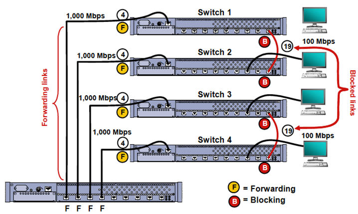
STA allows redundant physical links while logically disabling the paths that would cause loops. It also lets a network planner design and install redundancy in a network without creating loops. The basic steps in setting up STA are:
- Plan the network design and installation: Carefully document how the network is going to be designed and installed. Specifically note each link between switches.
- Enable STA on the switches: Many vendor switches have STA turned on by default.
- Select the root switch: This root switch is in the center of the network. All other switches recognize the root switch and each selects one path back to the root.
- Confirm convergence and operation: Each of the switches will now identify forwarding and blocking ports appropriately. The root switch sends out a BPDU (Bridge Protocol Data Unit) message every two seconds to inform all of the connected switches that everything is still okay. When a topology change takes place, such as a link failure, the affected switches recalculate their new best path back to the root switch.

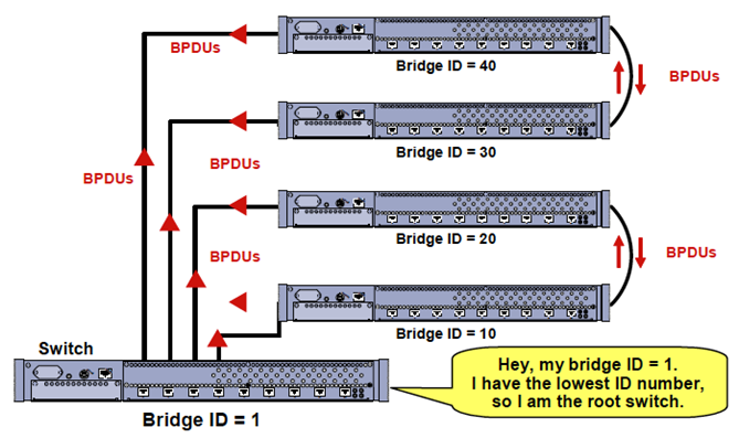
When you are designing a network, the root switch is the central connecting point for all of the connected switches. The administrator may designate which switch is to be the root or may leave the decision up to the switches.
To designate the root switch, assign it the lowest bridge ID number in the network. The root switch communicates with the other switches by sending its bridge ID number via a multicast IEEE 802.1D BPDU. By comparing its own ID number with the arriving BPDU’s bridge ID number, each switch can identify the root switch and the port to reach it.
The Bridge ID is a combination of Bridge Priority and the MAC address. At times, such as when installing new switches, more than one switch may have the same Bridge Priority value which is the lowest in the network. In that case, the lowest numbered MAC address, on those switches with the lowest Bridge Priority, breaks the tie. That switch, with the lowest Bridge ID, will become the root switch. The process of determining the root switch may take up to 30 seconds.
Leaving the root selection to the switches is less desirable. It takes the chance that a switch in the corner of the network may become the root switch. If that happens, network performance slows:
Related Courses
Understanding Networking Fundamentals
Internetworking Multilayer Switches
Network+ Prep Course (N10-005)


 Worldwide Locations


