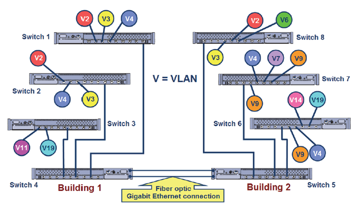
This short example illustrates basic VLAN operation. Examining VLANs in a large-scale installation can show the full benefits of VLANs. Consider that this is a small portion of a large corporate headquarters with 5,000 devices connected in a 20 building campus.
A large organization with many users at one location (5,000 to 10,000) may have hundreds of VLANs in place. The graphic is an example of some of the VLANs existing at a large scale VLAN implementation.
Configuring multiple VLANs that must communicate across multiple switches requires careful planning and consideration. Today, the most common method for connecting multiple VLANs on multiple switches is the IEEE 802.1Q Tagging Protocol.
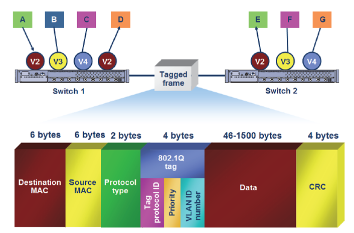
The IEEE 802.1Q Tagging Protocol is one method of connecting multiple switches with multiple VLANs. The sample configuration in above operates as follows:
- When a device on VLAN 2 sends out a broadcast, the frame is forwarded unchanged out to all of the ports on the switch that are configured for VLAN 2.
- The switch then inserts a tag or new field in the Ethernet frame, identifying the VLAN number. This tag is a 4-byte field.
- When the tagged frame arrives at the next switch, the switch removes the tag field and forwards the broadcast frame out to all of the ports configured for VLAN 2.
- If this second switch is connected to another switch, it tags the frame, indicating the VLAN, before it sends it out the trunk link.

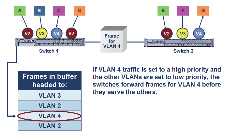
In addition to the VLAN identification number in the IEEE 802.1Q tag, there’s a field that lets a network administrator assign different levels of priority for different VLAN traffic. The assignment of different priorities helps when frames must sit in a buffer before transmission because of high traffic volume and where some of the traffic is time sensitive, such as voice or video. The VLANs using those applications would be configured as high priority and VLANs with large file transfers would be configured as low priority.
| Priority Level | Low | Medium | High |
| Setting | 0, 1 | 2, 3, 4 | 5, 6, 7 |
The IEEE 802.1P standard defines the levels of priority as shown. By default, most switches have all ports set to low priority until otherwise changed.
Related Courses
Understanding Networking Fundamentals
SWITCH — Implementing Cisco IP Switched Networks v1.0
Wireless LAN Foundations


 Worldwide Locations

